A two-part guide to HDD installation methodology. Part 1 covers project design, fluid design, and the pilot phase. Part 2 covers reaming sequences and the pipe pull — the stages where most bore failures occur.
The Challenge
The pilot phase is the most pressure-intensive stage of HDD. Insufficient pump rates increase cutting concentration and cause poor transportation. Annular pack-off in the small pilot hole induces hydrofracture. Once a hydrofracture occurs, fluid loss compounds through every subsequent phase. In the ream phase, pulling too fast creates an inadequate fluid-to-cuttings ratio, leaving cuttings beds that transfer directly to the pipe pull.
The Approach
Part 1 (Pilot): Design fluid for long transport times and significant grade changes. Maintain gel strength to keep cuttings in suspension during rod changes. Form a low-permeability filter cake tested with an API filter press. Apply lost circulation materials proactively during the pilot — this is when placement is most accurate. Part 2 (Ream and Pull): Match reamer style to formation type. Monitor pullback speed against slurry quality. Confirm bore is clean before starting pipe pull. For floating large-diameter pipe, ballast with water injection to sink pipe into bore centre.
The Outcome
A correctly sequenced bore clean eliminates the most costly HDD failure modes. Success indicators are specific: only drilling fluid with suspended cuttings during displacement means a clean bore. Large semi-solid cuttings indicate unremoved cuttings beds from reaming — the time to fix this is before the pipe pull, not during.
The Full Story
This is the first blog in our deliver better outcomes series.
Horizontal Directional Drilling is a common and popular method for installing underground infrastructure. Like all civil engineering methodologies, a scientific approach will reduce risk and increase certainty for the contractor and asset owner.
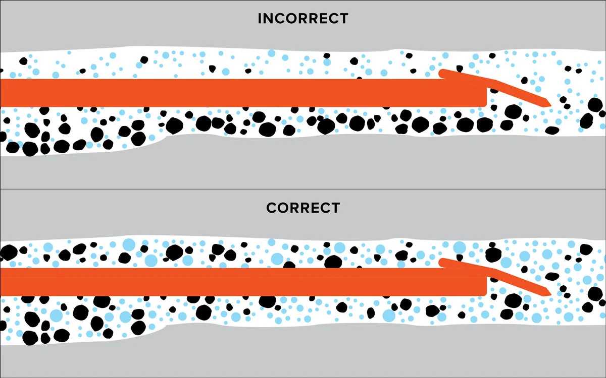
An HDD installation requires the contractor to progress through a number of stages (pilot, reaming and pipeline pullback), completing each step effectively to ensure the following stage can be completed. The steps are interrelated; challenges or poor procedures on one stage influence the following phase, and then may require alterations to the methodology to maximise success.
First, let's look at project design, fluid design and the pilot phase. Part 2 dives into reaming and pipe pull.
Project design
The design has a strong influence on the overall risk and cost of the project. A design which takes into account borehole length, depth, inclination angle, hole geometry, geology and rig capability is essential for a successful HDD installation.
Access to accurate relevant geotechnical data can improve the design substantially. This assists the HDD contractor with tooling selection, fluid properties, and drilling parameters, producing cuttings that can be efficiently removed from the borehole with reduced risk of hydro-fracture. Hydro-fracture, or frac out, occurs when drilling fluids escape from the borehole to the surface.
During the design phase, a qualified drilling engineer can provide valuable input, potentially reducing risk and providing a design that is easier and simpler to install. This can include using virtual hydraulics software to conduct a hydrofracture analysis, which can benefit the overall design, potentially lengthen shots, and provide greater security in waterways and sensitive area crossings.
Fluid design
The value that an effective drilling fluid brings to the job cannot be overestimated. Drilling fluid has a number of roles to play. These include transmission of hydraulic energy to the bit, lubrication and cooling, stabilisation of the borehole, and transporting cuttings out of the borehole.
One key role fluids play is maintaining cuttings in suspension during rod changes and when the pumps are turned off. Inadequate cutting suspension leads to cutting bed development, annular pack, and an increased risk of hydro fracture or stuck pipe. Here, the key is optimising the static gel structure formation, or the ability to gel and suspend cuttings, when flow ceases rapidly. The fluid's ability to rapidly gel when flow ceases is determined using a rotational viscometer.
An effective fluid will be designed to take into account the challenges provided by the design:
- a long installation length requiring extended cuttings transport time
- significant grade changes 'dog-legs'
- changes in bore geometry resulting in flow velocity fluctuations
- the size and concentration of the cuttings produced by the tooling and fluid jet impact force
To effectively transport cuttings, the HDD contractor must balance the drilling advance rate, pump flow rate and the fluid's dynamic Yield Point and low shear rate viscosity determined using a rotational viscometer.
Finally, drilling fluid allows the contractor to stabilise the borehole by applying pressure to the borehole walls and creating a filter cake that controls the flow of water across the borehole wall from the annular region. This control of water across the borehole wall is the primary tool for maintaining borehole stability. The biggest cause of instability is water crossing into the formation and destabilising it. Here, the key is the fluid's ability to form a low-permeability filter cake, which is evaluated using an API filter press.
The larger and more critical the bore, the more sophisticated the fluid design and management needs to be in both planning and executing the installation. In large-scale designs, early engagement with a qualified fluid engineer will provide valuable insight into drilling fluid design and drilling parameters required to provide an efficient hole-cleaning function.
The pilot phase
The pilot phase of the HDD process is often overlooked in importance, but it is critical to the success of the following reaming and pipe pull stages. Errors or bad practices during the pilot hole drilling have significant impacts on the successful reaming and pipeline pullback phases.
The pilot phase will be drilled using the most appropriate tooling for the formation. Access to geotechnical data allows an informed choice over the optimal tooling configuration. In hard ground, a mud motor might be selected, a rock bit for weaker rock formations, or a standard blade in softer soil and sands.
Drilling mud is pumped at prescribed volumes to remove the cuttings from the bore as the formation is cut by the drill bit. During this time, the newly established bore is at the most risk. The relatively narrow annulus created means that the downhole pressure is at its highest of any of the following stages of the HDD process.
If this fluid circulating pressure exceeds the formation fracture pressure, micro fractures will occur, allowing fluid to escape into the formation and potentially to the surface, causing infrastructure and environmental damage. The hole-cleaning function is heavily influenced by angular velocity. Still, flow rates are also proportional to pressure, so the pump rate must be planned and managed accurately during the pilot phase. Where insufficient fluid pump rates are implemented, the cutting concentration will be increased, and poor transportation will result. This can quickly lead to an annular pack-off in the small pilot hole and induce hydro-fracture.
The correctly designed drilling fluid, optimised for the specific borehole design, rig capabilities, tooling, and methodology, will result in good cuttings transportation from the borehole during the pilot phase and significantly increase the likelihood of a successful HDD installation.
Once the pilot bore has been successfully installed, and drilling fluids have circulated back to the rig, the reaming phase begins.
Part 2: reaming and pipe pull
In Part 1 we looked at project design, fluid design and the pilot phase. These steps are essential to allow the next stages to be completed successfully. In Part 2, we look at the ream and installing the pipe.
Ream
Following the pilot phase, a reamer is attached to the drill rods (most commonly at the far end of the bore), and pulled back towards the rig following the pilot hole. The style of reamer is influenced by the formation type. Hard rock requires a different design to sand or clay. Having good geotechnical data at the start of the tender process, allows the contractor to purchase the correct tooling, which may have manufacturing and freight lead times to contend with.
When planning the reaming phase, the speed at which the reamer can travel is related to the volumes of mud being pumped and the reamer's rotational speed. The formation needs to be cut to the appropriate size and mixed with the drilling fluid to enable it to flow out of the bore. The correct ratio of reaming speed and pump volume allows the cuttings to be turned into a thin slurry, which will flow easily along the bore to the exit pit.
During reaming, attention should be given to the mud level in the pits. Typically, the mud level will be slightly higher than the crown of the bore to provide hydrostatic pressure and help stabilise the bore. Managing these levels is critical to controlling pressure within the bore and enabling effective cutting transport.
Observing the cuttings flow into the pit can provide information on how successful the reaming is. A cuttings flow with a thin flowing consistency, suspended cuttings, and substantial flow shows the correct ratio of fluid to cuttings. This will generally result in a clean bore. A cuttings bed, which is too thick to flow but is rather extruded in a sausage-like fashion, indicates the fluid-to-cuttings ratio is out of balance.
In a larger diameter bore, many contractors will use fluid recycling systems to reuse water and drilling fluid additives. Recycling fluid has economic advantages by enabling the reuse of large volumes of fluid and chemicals. It also has environmental advantages by reducing project volumes. The benefit of having our qualified drilling fluid engineer on site is around regular fluid testing, observing changes in real-time, and making adjustments to bring the drilling fluid back to specification.
Pipe pull
The pipe can be installed once the contractor is confident the bore is clean.
Large-diameter pipe can float when it enters the bore, causing friction between the top of the pipe and the bore roof. This can increase resistance to the pressure the drill places on the pipe, damage the pipe, or damage the bore, potentially altering the grade. To prevent this, the pipe can be ballasted in. Our qualified drilling fluid engineers can calculate a ballast solution whereby water is pumped into the pipe as it is installed, intending to sink the pipe into the middle of the bore. If the bore is clean, the pipe will be installed with very low pullback pressure on the drill.
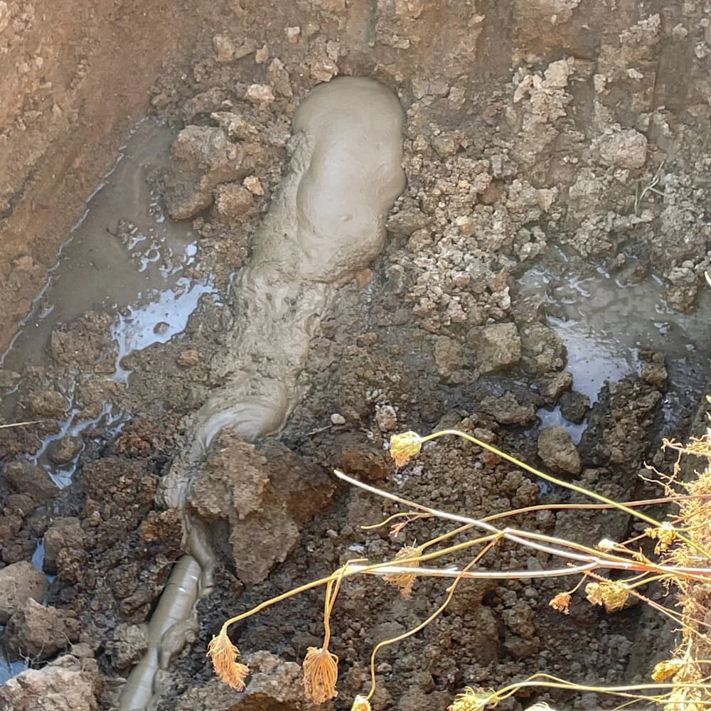
The preference is to be more effective at cleaning the hole on the pilot and reaming passes so that when it comes to pipe pull, there is only limited material to clean from the hole, and pressures can be maintained at a low level.
From the design to the installation of the pipe, each phase of the drilling process contributes to the success or otherwise of the next phase. There are a myriad of technical details and challenges to solve, as well as opportunities to improve the quality of the installation and provide greater value for money to the asset owner.
We work closely with councils, engineers, and contractors on all stages of the design and installation process. If you would like to talk through any stage of your HDD installation process, whether it's project design, fluid design, the pilot phase, reaming, pipe pull, or the whole process, give us a call.